

Reducing lead time in product development through standardization
The time or “lead time” from product conception to market launch is one of the most important factors in ensuring a company's competitive capability and expanding its market growth opportunities. It can determine whether the company will be the pioneer or a fast follower in certain market segments or niches.
The concept of standardization is used in manufacturing to maintain process stability, ensuring that activities are always performed in a given sequence and in the same way, within a given time interval and with the lowest level of waste, achieving high quality and high productivity. It is the basis for future improvements, eliminating more waste and shortening the lead time even further.
Applying standardization to product development also provides a significant reduction in “lead time”, as it avoids waste such as waiting, searching and correcting information, which cause rework both in the design area and later in manufacturing.
This article presents a method for carrying out “kaizen” in product development, in particular to reduce “lead time” through the use of the standardization concept.
1. Identifying the products with the longest “lead times”
First, we must identify which product has the longest development “lead time” in order to later analyze how to reduce it. We will consider “lead times” for the same category or nature of development, for example, small, medium or complete product change.
We can identify the types of products and their respective development “lead times”, and we may then have a chart similar to the one below:
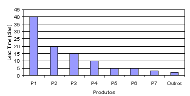
Chart 1 – “Lead Time” by product
We note that product P1 has the longest design lead time. These are usually the more complex products, with several sub-components.
Defining the product with the longest lead time can help prioritize improvement efforts. Other economic, financial and strategic factors may be equally important in defining the product to focus on, but a long lead time tends to signal relevance and high cost.
2. Identifying the activities involved
Once the product (or product family) has been identified, we must then identify* the steps or processes this product goes through. At a macro level, we can cite the case below as an example, simply listing the activities and their respective “lead times”, as shown in table 1.
| Activities | LT (days) |
1 | Meet with customer | 1 |
2 | Approve specifications | 2 |
3 | Carry out basic design | 5 |
4 | Generate drawings for approval | 8 |
5 | Inspect drawings | 1 |
6 | Correct drawings | 5 |
7 | Approve basic design drawings | 1 |
8 | Generate detailed drawings | 15 |
9 | Inspect drawings | 1 |
10 | Approval of final drawings | 1 |
| TOTAL: | 40 |
Table 1 – Activities for product 1
3. Analyzing the activities with the longest “lead time”
Representing the macro processes and their “lead times” in descending order, we observe that step 8 (Generate detailed drawings) and step 4 (Generate drawings for approval) account for almost 60% of the total “lead time”.
If we analyze the drawing generation activities in more detail, looking at the proportion between the number of reused drawings, that is, those taking advantage of files from previous projects, and those made completely from scratch, we can observe the following result:
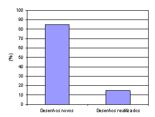
Chart 2 – New vs. reused drawings
We then ask why so many new drawings need to be generated, why the drawing reuse rate is low, and whether it would be possible to reduce this effort, which consumes so much time and resources, without harming the quality of development. Almost always the conclusion is that the lack of standardization of certain technical specifications leads designers to make a new drawing for each new product designed.
4. Standardization plan
Therefore, we consider an effort to increase standardization necessary, in order to increase the drawing reuse rate and thereby reduce the total “lead time”.
To do this, it is important to get the support of the most experienced designers to draw up a plan for standardizing technical specifications such as dimensions, tolerances, and to define which items will be standardized. Figure 1 shows a model part with its dimensions A, B, C, D, E, F and G.
Next, we seek to create dimension tables with standard dimensions (table 2) for the various possible components, based on studies using tools such as relationship diagrams between these dimensions (chart 3).
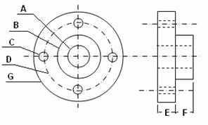
Figure 1 – Model part
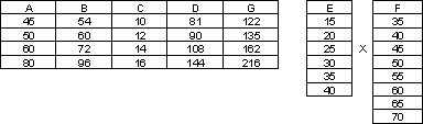
Table 2 – Standard dimensions table
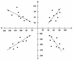
Chart 3 – Relationship diagram between dimensions
With this, a database of CAD models with standard dimensions can be generated. Figure 2 shows the standard CAD drawings available, with no need to redraw them. The goal is not to draw the component for each new product, but rather to copy and paste, taking advantage of these standard models, thus reducing the lead time for producing new drawings. The more standards there are, the shorter the step of generating drawings for approval or producing detailed drawings will be. It will also help in the manufacturing phase, including in terms of machine setup, since it reduces the time spent on unnecessary adjustments for each new product.
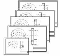
Figure 2 – Standard CAD models
In the case of chemical, food and other industries that do not use detailed drawings to manufacture their products, standardizing measurements may not apply, but rather standardizing specifications and technical information on formulations, packaging, among others.
5. Other types of standardization
The reason long “lead times” occur is the existence of waste in the activities of the development process. One of the most common wastes is the time spent searching for information, especially missing technical specifications sent by the Sales department after negotiation with the customer. A lot of rework happens when designers proceed with the design based on assumed specifications because of their absence.
Another frequent waste is the rework generated when drawings reach Production with specifications that are not compatible with manufacturing. This happens because Sales accepts orders with customized customer specifications without consulting the Development and Manufacturing department about their implications for product development.
To eliminate this rework and loss of time, order request forms should be improved or created, standardizing certain fields. Prepare a manual for sales staff with the pre-established product specifications with standardization already incorporated. Hold training sessions and meetings between Development and Sales staff to explain these standards.
Many may argue that rework, or changes in specifications during the project, are activities that add value, since the effort is made, in many cases, to improve the performance of the final product. However, these actions cause various types of waste both for the company and for its suppliers. For example, they generate:
1. Materials that are no longer used;
2. Components that become obsolete;
3. Replacement of tooling to meet the new product specifications;
4. Waiting for new item orders to be issued;
5. Waiting for new deliveries;
6. Reassembly of the new component or product;
7. Re-inspections;
6. Measuring and tracking “lead time”
We can only improve something when we can measure it. One of the important indicators to be measured is Schedule Tracking, given by the ratio:
Target project lead time
Current project lead time
This is because in the factory an entire production line can stop for want of a single missing drawing. If this value equals “1”, the project is on schedule. A value less than “1” means the project is late, and a value greater than “1”, ahead of schedule.
7. Conclusion
Standardizing component specifications in the development process is one of the most important elements in reducing “lead time”. It serves to eliminate the noise and waste generated during product development.
The steps presented in this article can be useful for seeing and exposing waste and attacking the root cause, benefiting the product development process by reducing development lead time and, as a consequence, total costs. These practices can be considered a basic step for many companies, similar to the basic stability (5S, improved machine availability, etc.) needed at the start of a lean transformation in manufacturing.
A broader approach, continuing this effort, would include the use of value stream mapping in product development processes and the inclusion, in the future state, of elements of the lean development system, such as set-based concurrent engineering, leadership by entrepreneurial system designers, decentralized planning with cadence and pull flow, and frequent interactions between the responsible teams of specialists, where the focus is on creating a profitable value stream and reusable knowledge that meets customers' needs.
Bibliography
*For more on how to draw the value stream map for product development, see Liker, J. K. and Morgan, J. M. The Toyota Product Development System: Integrating People, Process And Technology, Productivity Press, 2006.
Kennedy, M. N. Product Development for the Lean Enterprise, Oaklea Press, 2003.
Marchwinksy, C and Shook, J (eds.). Lean Lexicon. Lean Institute Brasil, 2003.
Sekine, K., Arai, K. Design Team Revolution, Productivity Press, 1994.
Ward, A. C. The Lean Development Skill Book. Ward Syntesis, 2002.